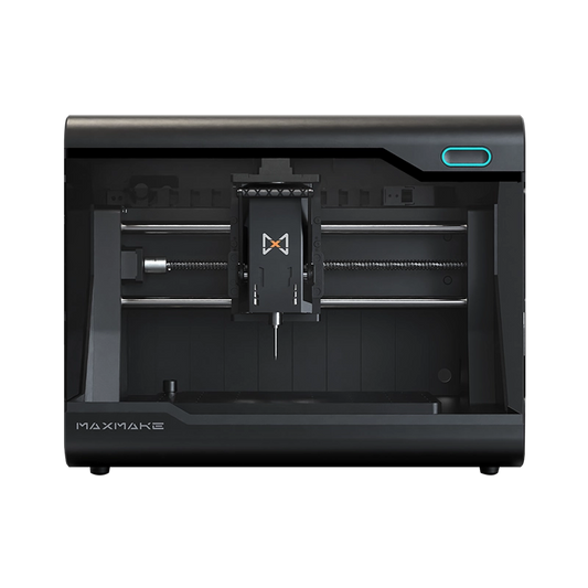
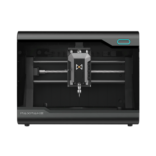
Desktop CNC Workflow: A Step‑by‑Step Guide for Beginners
Want to turn your ideas into precise physical parts? This section: CNC can feel overwhelming for beginners. This guide walks you through the complete desktop CNC workflow — from design to finished part.CAD modeling and CAM toolpath translation to G-code generation.You'll learn bullet list everything from CAD modeling and CAM toolpath generation to how to output G-code, plus WCS setup and workholding. Regardless of your machine type, mastering this standardized process ensures your digital manufacturing is efficient and precise.
What is the CNC Workflow?
Here's how a typical desktop CNC job flows from start to finish:
It begins with CAD (Computer-Aided Design) software, where you create 2D or 3D geometry. The CAD environment defines the part’s shape, dimensions, and features. It does not define how the machine cuts; it only defines the final geometry.
Most CAD software supports multiple file formats. For CNC, they fall into two buckets: 2D vectors and 3D models.

Phase 1: Design — Working with 2D and 3D Geometry
2D File Formats: DXF vs SVG for CNC Work
2D files are used for contour cutting, pocketing, drilling, and engraving. They contain planar geometric information without thickness or volume.

Short for Drawing Exchange Format, DXF is the industry standard for exchanging engineering drawings.

SVG files describe shapes with mathematical curves (not pixels), so they scale infinitely without losing quality. In CNC, SVG is great for contour cutting, engraving text, and sign making.
Think of it this way: DXF is for engineers (precision, dimensions), SVG is for designers (scalable, artistic). Mechanical work → DXF. Signs, text, art → SVG.
3D Model Formats
When a part includes complex surfaces or 3D structures, 3D formats are required.
A mesh-based format describing surfaces using triangles. It is common for 3D reliefs and artistic carvings. Keep in mind: Mesh resolution affects surface smoothness.

The industrial standard for precision CNC. Unlike STL, STEP preserves true mathematical curves (B-reps), allowing CAM to generate smoother toolpaths. It is the preferred format for mechanical parts.

Summary: 2D files define outlines and require depth input in CAM. 3D files define the full volume, allowing CAM to calculate paths based on the surface geometry.
Phase 2: The Logic Layer — CAM Planning & Strategies

CAM converts your CAD geometry into toolpaths that the machine can follow—the trajectory the tool follows relative to the workpiece coordinate system.
Stock Setup
In CAM, you enter your stock dimensions (X/Y/Z). This sets the virtual cutting boundary. Thickness matters: set it too thin and you won't cut through; set it too thick and you'll cut into your spoilboard. The origin (zero point) is typically at a corner or center — just make sure it matches where you'll set your zero on the actual machine.
💡 Set your stock depth 0.1-0.2mm deeper than the part in CAM, and make sure your spoilboard is flat.
Workpiece Origin (Zero Point)
The work coordinate origin is the reference point for all toolpath calculations. Every X, Y, and Z move in the toolpath is relative to this zero point.
Set your workpiece origin here, matching where you positioned it in CAM.

Tooling Parameters
Choosing the correct tool and matching it with technical parameters.

Define diameter, flute length, and type (End mill, Ball nose, V-bit).
Diameter: Determines the tool compensation path and the smallest internal corner radius (e.g., a 6mm tool can't cut a corner tighter than 3mm).
Speeds & Feeds:
Spindle Speed (RPM): Must match the material and tool diameter. Too low causes instability; too high causes excessive wear or heat.
Feed Rate: The horizontal movement speed. Too fast causes tool breakage; too slow causes material burning.
Step-down & Step-over:

Step-down: Layered cutting (e.g., cutting 12mm deep in 4 passes of 3mm each) reduces load and vibration.
Step-over: Lateral distance between passes. Smaller step-over improves finish but increases time.
Leads & Safety:
⚠️ Safe Height: Always set your retract height above your workpiece AND above any clamps — this is the #1 thing beginners get wrong.
Entry Strategy: Ramping or helical entry is preferred over vertical plunging to reduce axial impact.
Machining Strategies

Use this when cutting along the inner or outer boundary of a shape.

Use this when clearing all material inside a closed boundary layer by layer.

Use this when vertical movement at specific points for round holes.

Use this when shallow cutting along the centerline of a path.
Phase 3: The Execution Layer

Once the G-code file is generated, transmit it to the CNC controller.
Use a G-code Sender (e.g., gSender, Candle) to transmit the file via USB. Key functions include:


Hardware Setup: Clamping & Tool Installation
Tool Installation

Workpiece Clamping


Clamping prevents movement under cutting forces.
Coordinate Systems: MCS vs. WCS
💡 One-Sentence Summary: Machine coordinates answer "Where is the machine?"; Work coordinates answer "Where is the part?"
Formal Machining: Dry Run & Monitoring
Dry Run

Run the full program with the tool raised above the material. This confirms your coordinates are correct — and that the tool won't crash into your clamps.
Starting the Job

Start the spindle and wait for it to reach full RPM. Keep the feed rate override low for the first few passes so you can watch the cut closely.
Appendix: Technical Reference
The Post-Processor
Think of the post-processor as a translator — it converts your CAM toolpaths into the specific G-code dialect your controller speaks (GRBL, Mach3, etc.). Make sure you've selected the right one, or your machine might not understand the instructions.
Common G-code Commands
| Command | Category | Description |
|---|---|---|
| G0 / G1 | Motion | Rapid Move / Linear Cutting |
| G2 / G3 | Motion | Clockwise / Counter-clockwise Arc |
| G17 / 18 / 19 | Plane | XY (standard), XZ, or YZ Plane Selection |
| G20 / G21 | Units | Inches / Millimeters |
| G90 / G91 | Mode | Absolute / Relative Coordinates |
| G54 - G59 | Offset | Work Coordinate System selection |
| G28 | Home | Return to machine reference point |
| G4 | Dwell | Pause for a specific time (e.g., G4 P2) |
| G43 | Offset | Tool Length Compensation |
| F / S | Parameters | Feed Rate / Spindle Speed |
| M3 / M5 | Spindle | Spindle Start (CW) / Stop |
| M30 | Program | Program End and Reset |
💡 Expert Tip: Use an independent G-code Viewer to simulate the file before cutting. This verifies the path is within machine limits and free of collisions.
Summary

A successful desktop CNC workflow is a closed loop:
CAD Design → CAM Planning → Post-Processing → Sending G-code → Homing → Setting Zero → Clamping → Dry Run → Physical Cutting → Quality Inspection.
Each stage is the foundation for the next. Following this standardized workflow is the most reliable way for beginners to transition to high-precision CNC manufacturing.
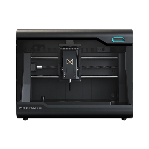
HiMill D1S - Pro Desktop CNC with Ball Screws & QTC
Connect with the MAXMAKE community
Share your projects, discover new ideas, and connect with other makers.
Join Our Community
Share projects, ask questions, connect with makers