CNC Feeds and Speeds: A Beginner's Guide to CNC Machining
Quick Answer
CNC feeds and speeds are the cutting settings that control how fast a CNC tool moves through material and how fast it rotates.
The two main settings are Feed Rate — how fast the tool moves — and Spindle Speed — how fast it rotates. Chip Load describes how much material each cutting edge removes, and Cutting Speed (Vc) is used to work out an appropriate spindle speed.
There is no single correct setting: the right values depend on the material, the tool, the machine, and the depth of cut. Beginners should start from tested or conservative values and adjust based on the cut. This guide explains each parameter, how they work together, and how to tell when a setting is wrong.
CNC Parameters vs. 3D Printing and Laser Cutting
If you're familiar with 3D printing or laser cutting, CNC feeds and speeds can seem more complicated at first. The basic idea is similar: you are controlling how a machine performs a process.
| Machine | Common parameters |
|---|---|
| 3D Printer | Print Speed + Nozzle Temperature |
| Laser Cutter | Cutting Speed + Laser Power |
| CNC Machine | Feed Rate + Spindle Speed |
The difference is that a CNC cutting tool physically contacts the material and rotates while moving through it. Think of a handheld rotary tool carving wood: the bit spins while your hand moves it across the surface. Those are two separate motions — the tool rotating (Spindle Speed) and the tool moving through the material (Feed Rate). Keeping them separate makes the rest of this guide easier to follow.
What Are CNC Feeds and Speeds?
The phrase "feeds and speeds" sounds like one setting, but it describes several related cutting parameters.
Feed Rate
Feed Rate is how fast the cutting tool moves through the material along its cutting path, measured in mm/min or in/min (IPM). A feed rate of 1,000 mm/min (39 IPM) means the tool travels 1,000 mm of toolpath in one minute. Feed Rate is also called feed speed, and it is the parameter most beginners get wrong — usually by setting it too low.
Spindle Speed
Spindle Speed is how fast the cutting tool rotates, measured in RPM (revolutions per minute). Feed Rate and Spindle Speed are separate controls: you can change one without changing the other. During a cut, though, they affect each other, because changing either one changes how much material each cutting edge removes.
Chip Load
Chip Load describes how much material each cutting edge removes during one revolution of the tool. It is how Feed Rate, Spindle Speed, and the number of flutes are connected:
Chip Load = Feed Rate ÷ (RPM × Number of Flutes)or, rearranged:
Feed Rate = RPM × Chip Load × Number of FlutesChip load is the most useful number for judging whether the tool is cutting or rubbing. A tool that rubs generates heat instead of chips — one common reason for burning, melting, or excessive dust.
Cutting Speed (Vc)
Cutting Speed (Vc) — also called surface speed — describes how fast the cutting edge moves across the surface of the material, and it depends on tool diameter and Spindle Speed. It is the value you use to work out RPM:
RPM = (Vc × 1000) ÷ (π × D)   (metric: Vc in m/min, D in mm)
RPM = (Vc × 12) ÷ (π × D)     (imperial: Vc in ft/min (SFM), D in inches)
This is why a larger tool generally needs a lower RPM than a smaller tool at the same cutting speed. For beginners, the important distinction is that Spindle Speed (RPM) is the value you enter in your CNC software, while Cutting Speed (Vc) is the material-driven value used to work out what that RPM should be.
Plunge Rate
Plunge Rate is how fast the tool moves downwards along the Z axis as it enters the material. It is not the same as Feed Rate and should not be set to the same value: when the tool moves sideways, only part of the cutting edge is engaged and chips can escape, but when it plunges straight down the center of the tool has almost no cutting speed. Plunge Rate is typically 25–50% of Feed Rate, with one third a good starting point. Tools that cannot plunge — many down-cut and some V-bits — need a ramp or helical entry. And drilling is not plunging: a drilled hole needs a drill, with its own parameters.
Stepdown and Stepover
Stepdown and Stepover describe how much material is removed at once, and they change the load on the tool even when every other setting stays the same. Stepdown is the depth of each Z-level pass; Stepover is the horizontal distance between two adjacent toolpaths, usually given as a percentage of the tool diameter. A deeper or wider cut means a heavier load, and the two trade against each other — raising both at the same time is one of the fastest ways to break a tool on a light machine.
How Do Feeds and Speeds Work Together?
Feed Rate and Spindle Speed are independent motions that interact during the cut, and Chip Load is what connects them:
- Raise Feed Rate, with RPM and flutes unchanged → each cutting edge removes more material → higher chip load
- Raise RPM, with Feed Rate and flutes unchanged → the cutting edges pass more often → lower chip load
- Use more flutes → the same feed is spread across more cutting edges → lower chip load per flute
- Use a larger tool → at the same Cutting Speed, a lower RPM is needed
So "calculating feeds and speeds" means using these relationships in sequence: pick a Cutting Speed for your material, convert it into RPM for your tool diameter, choose a chip load your tool can take, then calculate Feed Rate. For a 3.175 mm (1/8 in) two-flute tool in aluminum at 7,500 RPM and a target chip load of 0.025 mm per tooth, that works out to roughly 380 mm/min (15 IPM).
The goal is not to cut as fast as possible. It is to find a stable condition where the tool removes material efficiently without excessive heat, vibration, rubbing, or load.
How Do You Choose the Right Feeds and Speeds?
There is no single Feed Rate and Spindle Speed that works for every job. The right starting point depends on four things.
Material
Different materials require different cutting conditions. Wood, acrylic, and aluminum respond differently to heat, chip evacuation, and cutting force: aluminum conducts heat into the tool and can weld to the cutting edge if chips are not cleared, acrylic softens and re-welds behind the tool if it gets too warm, and wood cuts easily but burns at low feed rates.
Tool
Tool diameter, number of flutes, cutting length, tool material (HSS vs carbide), and tool sharpness all affect the appropriate settings. Excessive tool overhang increases deflection, chatter, and the risk of tool breakage, so keep the tool as short in the collet as the job allows.
Machine
Machine rigidity, spindle power and its usable RPM range, workholding, and tool overhang determine how aggressively the machine can cut. A rigid machine can handle conditions that are too aggressive for a less rigid one — which is the main reason the same parameters work on one desktop CNC and fail on another.
Depth of Cut and Toolpath
A deeper or wider cut creates more load, even when Feed Rate and Spindle Speed stay the same. If a cut becomes unstable, reduce stepdown or stepover before making large changes to Feed Rate or Spindle Speed.
The right settings come from the combination of machine + material + tool + cutting conditions.
CNC Feeds and Speeds Chart: Starting Values by Material
There is no single feeds and speeds chart that works for every machine. Starting values depend on the material, the tool diameter, the number of flutes, spindle capability, machine rigidity, and toolpath — so treat any chart as a starting point, not a rule.
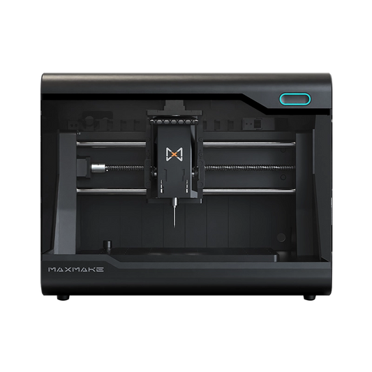
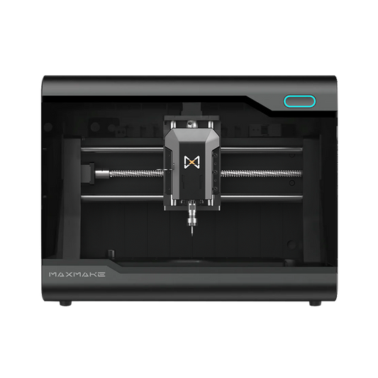
The table below lists the parameters we run on our HiMill D1S desktop CNC. Use them as a starting point on machines with similar spindle capability, then fine-tune after a test cut. Values by bit diameter are in the tool parameter tables.
| Parameter | Aluminum | Acrylic | Pattern Wood | PCB Board |
|---|---|---|---|---|
| Tool Selection | 3-Flute Carbide End Mill for Aluminum | Single Flute Spiral Bit | Standard Double-flute Solid Carbide Flat End Mill | Corn Cob End Mill |
| Spindle Speed | 12,000–13,000 RPM | 10,000–13,000 RPM | 12,000–13,000 RPM | 12,000–13,000 RPM |
| Feed Rate | 100–200 mm/min | 600–800 mm/min | 1,000 mm/min | 800–1,000 mm/min |
| Stepdown | 0.1–0.3 mm | 0.5–1.0 mm | 1.0–3.0 mm | 0.05–0.2 mm |
| Stepover | 0.5–1 mm | 0.1–1.5 mm | 0.5–2 mm | 0.5–1.0 mm |
| Plunge Rate | 50–100 mm/min | 400–600 mm/min | 500–800 mm/min | 400–800 mm/min |
How Do You Know If Your Feeds and Speeds Are Right?
You don't need to calculate perfect settings before your first cut. Start from a known parameter set, run a test cut, and watch how the machine, tool, and material behave.
What Should a Good Cut Look Like?
A good cut generally has:
- Consistent chips rather than only fine dust
- No excessive burning, melting, or heat
- Limited chatter and vibration
- A reasonably clean surface finish
- A tool that stays stable and does not become excessively hot
Which Parameter Should You Adjust First?
Adjust one parameter at a time, or you won't know which change helped.
| Symptom | What to check first |
|---|---|
| Burning wood or melted acrylic | Feed rate, spindle speed, tool sharpness, chip evacuation |
| Fine dust instead of chips | Feed rate, chip load, tool condition |
| Chatter or vibration | Stepdown, stepover, tool overhang, workholding |
| Tool breaks during entry | Plunge rate, ramping, entry method |
| Tool breaks during cutting | Depth of cut, feed rate, tool overhang, workholding |
| Poor surface finish | Stepover, tool condition, machine rigidity |
A single symptom can have more than one cause, so treat the table as clues rather than fixed rules. If several problems appear at once, reduce Feed Rate or Stepdown by 20–30% and re-test. Write down what worked — it becomes your own parameter library.
If the tool itself looks worn, chipped, or gummed up, see our desktop CNC maintenance guide.
Finding Your Starting Feeds and Speeds
You don't need to calculate everything from scratch. Follow this order:
- Identify the material.
- Identify the tool diameter and number of flutes.
- Check the machine or tool manufacturer's tested parameters.
- Start conservatively.
- Run a small test cut.
- Adjust one parameter at a time.
The fastest route is the MAXMAKE tool parameters guide, which gives tested starting values per material and tool. If you use MAXMAKE software, its built-in parameter library provides the same values.
Before and after this step: our CNC router bits guide covers choosing the tool, and the step-by-step desktop CNC workflow covers everything from file to finished part.
And remember: a manufacturer's numbers describe capability, not a guarantee. Treat every published value as a starting point and confirm it with a test cut.
Frequently Asked Questions
What are feeds and speeds in CNC?
CNC feeds and speeds are the cutting parameters that control how the tool moves through the material and how fast it rotates. Feed Rate controls the tool's linear movement, Spindle Speed controls its rotation, and Chip Load connects the two.
How do I calculate CNC feeds and speeds?
Choose a cutting speed (Vc) for the material, convert it to RPM with RPM = (Vc × 1000) ÷ (π × D) for metric or RPM = (Vc × 12) ÷ (π × D) for imperial, then pick a chip load per tooth and calculate:
Feed Rate = RPM × Chip Load × Number of FlutesSet Plunge Rate to about one third of Feed Rate and start with a conservative Stepdown.
What is a good feed rate for CNC?
There is no universal feed rate. The right value depends on the material, the tool (diameter and flute count), the machine, and the cutting conditions. Instead of looking for a single number, start from a conservative value for your material and tool, then adjust based on the first cut.
Should I increase Feed Rate or Spindle Speed?
The goal is to maintain an appropriate chip load for the tool. If the tool is rubbing — burning, melting, or producing dust — increasing Feed Rate or reducing RPM may help, but also check tool sharpness and chip evacuation. If the cut is straining or chattering, the load may be too high, so reduce Feed Rate or Stepdown.
Can I use the same feeds and speeds for wood, aluminum, and acrylic?
No. Different materials require different cutting conditions, and the tool, machine, toolpath, and depth of cut also affect the right values. Use material-specific starting parameters rather than one setting for every job.
Why is my CNC burning wood or producing dust instead of chips?
Burning, melting, or excessive dust can indicate that the tool is rubbing instead of cutting efficiently. Check chip load, feed rate, spindle speed, tool sharpness, and chip evacuation. Raising Feed Rate gradually is usually the first thing to try, rather than adding RPM.
Why does my CNC bit keep breaking?
Tool breakage can result from excessive cutting load, too aggressive a depth of cut, poor workholding, excessive tool overhang, vibration, or unsuitable Feed Rate or Spindle Speed. Where to look first depends on when it breaks: on entry, check Plunge Rate and the entry method; mid-cut, check depth of cut first, then Feed Rate; if it breaks repeatedly in the same spot, check tool overhang, machine rigidity, and tool condition.
Do I need a feeds and speeds calculator?
Calculators are useful for the arithmetic, but they only work on the numbers you give them. You still need a cutting speed for your material and a chip load for your tool, and the result still has to be adjusted for your machine, tool, material, and toolpath. Use a calculator to save time, then confirm with a test cut.

HiMill D1 Desktop-CNC-Maschine
Connect with the MAXMAKE community
Share your projects, discover new ideas, and connect with other makers.
Join Our Community
Share projects, ask questions, connect with makers